Friday, December 31, 2010

Subpanels—a Real Convenience


Subpanels are smaller versions of your main service panel. They serve a couple of purposes:
  • They provide proximity to circuit breakers, especially in large homes, so you don’t have to access the main panel some distance away.
  • They can expedite the wiring of a large house because the electrician only has to run one feeder cable from the main panel to the subpanel instead of running cable for every circuit separately the same distance. A subpanel on the second floor of a large three-story house, for example, enables you to control the circuits on the second and third floors. Like your main panel, you have to follow a few rules regarding the location of a subpanel:
  • It cannot be installed in a bathroom.
  • It cannot be installed in a closet.
  • The subpanel must be in an accessible, visible location.

Breaker, Breaker


Circuit breakers, along with fuses, are known as overcurrent protective devices. They protect you, your electrical equipment, and your wiring. They are matched to the ampacity of a circuit’s conductors, and they shut the current down if there’s an overload or a short-circuit. Breakers are clearly marked (15, 20, 30 amp, and so on) and must be used accordingly. You can’t stuff a 20-amp breaker into your panel box and use it on a 15-amp circuit, especially if the circuit only has 14-gauge wire. This is a recipe for fire because you’ll be allowing the wire to carry more current than it’s designed to carry, and the breaker won’t sense the problem and thus won’t trip.
Breakers are either single pole or double pole (sometimes referred to as a two-pole breaker). Double-pole breakers are used for 240-volt circuits and draw power from each of the 120-volt hot wires entering the panel. A double-pole breaker can be either a single device or two single-pole breakers tied together so they’ll both shut off at the same time.

Grounding Your Panel


A big safety advantage in newer service panels over old fuse systems is the fact that they’re grounded. The code is very specific about grounding procedures including

➤ The size of the grounding conductor.
➤ What is and is not an acceptable grounding electrode.
➤ Bonding requirements and the use of clamps and bonding bushings.

A service panel is grounded twice when possible: once to your water pipes (assuming they’re metal and not plastic) and once to a grounding rod buried in the ground. When a grounding rod cannot be used due to soil conditions, a length of copper wire can be buried directly in the earth (a minimum of 21/2 feet deep) or encased in concrete at least two inches thick that has direct contact with the ground (usually a foundation).
There also are other means of grounding the system (depending on your soil and house construction). The materials allowed, their installation, and their dimensions are all spelled out extensively in Article 250 of the code. Electricians know this stuff by heart because they use it every day. You, on the other hand, will never use it again, so consider calling an electrician for your panel installation.

Tuesday, November 30, 2010

Location Is Everything

The code is a little particular about where you can situate a service panel. In addition to being as close as possible to the service conductors’ entry point, a service panel …

➤ Must have clear access to it (a minimum of a 30-inch wide by 36-inch deep uncluttered space).
➤ Cannot be installed inside cabinets or above shelving or any other encumbrance. It also cannot be installed in a bathroom.
➤ Must have a working space with 61/2 feet of headroom around it.

In other words, the panel has to be in a clear and accessible area, and it must be readily visible to anyone looking for it. You can’t store your skis or bikes in front of it, and you must be able to open the panel door a full 90 degrees until it’s flat against the wall. Section 110-26(d) of the NEC calls for some illumination to be provided around the panel so that you or an electrician can see what you’re doing if you have to access the panel. Although the code doesn’t detail how much lighting you need to supply, you want to be able to comfortably read the panelboard (the breakers) and the panelboard directory inside the door.

Anatomy of an Electrical Service Panel

A service panel must conduct electricity to individual breakers, must receive and
route the current being returned through the neutral conductor, and must provide a
grounding medium for the system. In a sense, it’s the most powerful electrical device
in your system. Remember, the conductors and cable that come into and leave your
service panel include …

➤ Two hot conductors.
➤ One neutral conductor.
➤ One grounding conductor that

originates in the panel. The two hot conductors energize the panel—and thus the breakers—via two hot bus bars, which are located in the center of the panel. The black or red outbound wires are connected to the circuit breakers that clip or slide into the hot bus bars. These wires supply the current to electrical loads throughout your house. The neutral wires are connected to the neutral bus with setscrew terminals. A grounding bus bar connects the various grounding conductors from the circuits to the panel’s main grounding conductor. The grounding bus bar is bonded to the neutral bus bar. This is the only place the neutral and grounding conductors are tied together. In addition to individual breakers, most service panels have a single main service disconnect in the form of an individual breaker or a series of high-amperage breakers connected together. The code requires that you be able to shut the entire panel down with a maximum of six hand movements. (That is, the panel can’t need more than six switches or breakers to disconnect all of your home’s electrical equipment.) An old panel might require up to six moves to shut everything down, but new service panels all have a single main shutoff, as previously described. The code requires that this main disconnect be as close as possible to the service conductors’ point of entry into the building. In other words, you can’t bring the service conductors into one corner of your basement and then install the service panel 15 feet away while exposing the conductors. (Certain exceptions do apply.)

New Service/Old Service Electrical Service


Unless you’re rewiring your entire house (which isn’t likely unless you’re doing a major remodel), you’ll need to connect your new service panel with at least some of the existing circuits. This usually is not included in the cost of the service change. It really depends on the purpose of the upgrade. In addition, if you have an old fuse system, you will most likely replace the following (again, at an extra cost):

➤ The major appliance circuits
➤ The kitchen and bathroom circuits
➤ The water heater and possibly the furnace circuits

Existing branch circuits for lighting often can be left alone and simply tied into your new panel. (Each will have to be checked, of course.) If you are replacing an existing service panel on a three-wire grounded system with a higher-amp panel, you also will need to connect to the existing service. Only when you’re completely rewiring your home can you ignore the existing service and its location.

Sunday, October 31, 2010

Going Underground


I’m a big fan of underground service conductors. New developments almost always have them, but a new house in an established neighborhood might not, depending on which side of the street it’s located. If you’re on the same side as the utility poles, consider burying your line. It will involve digging a trench at least 18 inches deep (check local requirements) and possibly doing so across a neighbor’s property. A buried cable results in a much cleaner appearance, and there’s no chance of it being damaged during severe weather, massive flooding notwithstanding. (The utility’s power lines can still go down, however.) It’s also out of the way when you have to set up ladders to paint or to work on your roof.
With an underground service, your utility company installs service lateral conductors (which may or may not have to be contained in conduit, depending on your local code). The conductors then enter the meter, via at least a short section of conduit, from underneath the ground. As with any outdoor wiring done by an electrician, you can save yourself some money by doing the digging and trenching yourself or by hiring it out to a less-expensive laborer than an electrician.

Overhead and Exposed


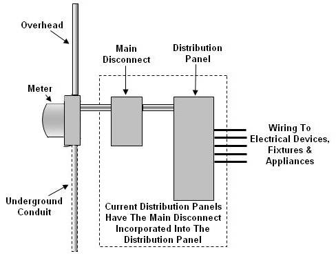
It’s a lot simpler to install an overhead service in an established neighborhood than it is to start tunneling under streets and sidewalks to run conductors underground. Overhead wires are exposed to the weather, however, and this means your service can be disrupted if a tree branch falls on it during a high wind. Modern electrical service consists of two hot conductors and one neutral conductor coming into your home. They come out of a transformer, which steps down the voltage, and must clear roofs, fences, and outside structures as they connect to your service head on top of your service mast. The conductors form a drip loop as they enter the service head so that any rain landing on them will not run down the mast.
The service conductors are pulled through the mast and then pass through the meter (which records your electricity usage). Your utility connects the wires coming out of the weather head to the conductors (service lateral conductors or overhead wires) coming from the pole and the conductors to the meter, which the company usually supplies. Rules for installing an overhead service govern …

➤ The location of the meter.
➤ Clearance requirements for the conductors.
➤ Securing and supporting the service mast and raceway to your house.

Your utility company determines where the meter will be located. The company’s main concern is that the overhead conductors will be in a safe, unencumbered location. The clearance requirements for the conductors and the length of your service raceway (the mast and head) must take the following factors into account:

➤ The distance from the service mast to the utility pole
➤ The pitch of your roof
➤ Whether you’re using an IMC, PVC, or steel raceway (conduit)
➤ The proximity of windows to the proposed location

Finally, the conduit or raceway must be secured properly so it doesn’t loosen or bend. Any hole you drill for the raceway or its supports must be sealed so you don’t get water leaks. Your local electrical inspector can give you more information about clearance requirements and securing your service mast.
As you can see, this is a complicated process—and we haven’t even gotten to the service panel yet! In case you were wondering, you can’t attach any other cables (phone or TV, for example) to your service mast.

One New Service Coming Up


Your service panel is the primary distribution center for all the electrical currents in your house and yard. It connects your CD player, lava lamp, and 27-speed blender to your utility’s service lines. Fuses serve the same purpose as the circuit breakers in a modern service panel, but they are considered dated and no longer are installed for residential purposes. Some old fuse services are as small as 60 amps, which is hardly adequate for modern electrical demands. The National Electrical Code calls for a new service to be a minimum size of 100 amps.
There are two types of electrical services:

➤ Overhead service
➤ Underground service

Most older services are overhead. That is, the utility company uses overhead service conductors, usually from a utility pole, that often connect to a service mast on the outside of your house. An underground service, commonly found in new housing, is buried. Each must follow prescribed installation procedures.

Thursday, September 30, 2010

What to Do When There are Power Outages?


You can’t do much to control power outages, but you can control what happens when the power comes back on. Unplug your computers and television sets, even if you have surge suppressors. The suppressors should take care of any initial charge from your electrical system, but unplugging these appliances guarantees that you won’t have any problems. Make sure any kitchen appliances that might have been left on, other than your refrigerator, are shut off. Any heat-producing appliance, such as an electric blanket, a heating pad, or a portable heater, also should be shut off, lest you forget about it and it stays on while you’re not home.

General Precautions in Working with Electrical Installation


Einstein considered common sense to be all the prejudices you acquire before the age of 18. (This was the belief of someone who apparently had to be reminded by his housekeeper to dress warmly before venturing out into Princeton winters.) Semantics aside, a certain amount of common sense should be applied to your electrical dealings.
Precautions for electrical appliances, devices, and wiring include the following:
  • Buy only items that are UL-listed or approved by another accepted testing agency.
  • Keep children from playing near portable heaters and kitchen appliances.
  • Use kitchen and bathroom appliances on or near dry surfaces only.
  • Keep combustible materials such as clothes and curtains away from heaters of any kind.
  • Never cut off the grounding pin from a three-pronged plug.
  • Never file down the larger prong on a polarized plug.
  • Use child-resistant caps in unused receptacles.
  • Install smoke detectors.
  • Make sure the contact between a plug and a receptacle is solid and tight.
  • Allow plenty of free space around computers, televisions, and stereo sound systems to prevent them from overheating.
  • Keep metal ladders away from all power lines.
  • Stay away from any downed power lines.
  • Have your electrical system inspected if it’s more than 40 years old and you have no record of a recent inspection.
  • Make sure all switches and receptacles have cover plates.
  • At the very least, install plug-in GFCI receptacles into existing bathroom and kitchen receptacles that do not have grounding.
  • Make sure light bulbs are the correct rating for their lamp or fixture. (Excessive heat can be a fire hazard.)
  • Unplug portable appliances when they’re not in use, especially those near sinks. (You can be electrocuted if they fall into water—even if they’re turned off.)
  • Leave electric blankets untucked.

Beware of Fire Hazards


Fuses and circuit breakers are designed to protect you from inadvertently overloading a circuit. When your loads demand more current than the circuit is designed to handle, the circuit breaker will trip or the fuse will blow. This prevents the conductors or wire from overheating and causing a fire. A conductor can only offer a certain amount of resistance to a current; if there’s too much current, the conductor can heat up enough to melt its insulation.
A homeowner can create a dangerous situation by replacing a fuse or a circuit breaker with one of larger amperage, thus allowing more current to flow through the wires than they can safely resist. A fire can start without tripping the breaker or blowing the fuse because the larger-amperage fuse cannot sense the problem. Some signs of a potentially overloaded system include …
➤ Thirty-amp fuses used for lighting circuits.
➤ The use of extension cords as permanent wiring.
➤ Dimming lights when appliance loads go on.
➤ Excessive use of adapters that allow more than two loads to be plugged into one receptacle.
➤ Multiple service panels and sloppy wiring practices.

Tuesday, August 31, 2010

Power Cords


Any cord-and-plug combination is subject to damage and wear. Lots of pulling and twisting, especially when a plug is pulled out by the cord rather than by grasping the plug itself, can cause the wires inside the insulation to break. This is particularly true with lamp cords because they use wire composed of multiple strands with a very small gauge. If the insulation protecting a cord cracks open, you could get a short circuit. It’s usually a better idea to replace these cords than to repair them.
Although it is less likely that you’ll ever have to replace a 240-volt appliance cord, these also can be changed out:
  • Unplug the cord and unscrew the end that’s attached to the appliance, noting which wire (by color) went with which screw.
  • Buy an exact replacement for the cord and plug.
  • Connect the new cord to the terminal screws on the appliance, noting any color coding on the screws to match the individual wires (black to black, and so on).

Short Circuits


One telltale sign of a short circuit is black, smoky residue on switch or receptacle cover plates. Frayed or damaged cords and plugs also can be sources of short circuits. You need to check further for the source of the problem if your circuit goes dead and …

➤ You cannot find any visible signs of an electrical short.
➤ The circuit is not overloaded.

Before replacing the fuse or resetting the breaker, turn off all the loads and unplug everything from the receptacles. If the new fuse blows or the breaker trips right away, your problem is either in one of the devices (a switch or a receptacle) or in the wiring itself. To make sure the current is dead, remove all the cover plates and examine each device for charred wires or black residue. Clip the ends of any affected wires, strip off sufficient insulation, and install a new device. Replace the fuse or reset the breaker, and test the circuit again.
What if the circuit doesn’t short immediately after you set the breaker or replace the fuse? In that case, activate each load one at a time and then turn each one off. Check the load that eventually causes the short. The problem will be either in the fixture or appliance itself or in its wiring. Replace the offender and check the circuit again. If it still shorts out, you have a problem in the wiring itself and should call an electrician. Shorts in the wire almost always are at the device or fixture box, so the problem should be visible when you do your own inspection. Sometimes, however, the problem is caused by a splice or junction box buried in the wall and is therefore unnoticed upon first inspection. In the case of a plug-in appliance or lamp, if the circuit goes dead as soon as you insert the plug, you can assume the short is in the cord or the plug (both of which can easily be replaced). If the short doesn’t occur until after the appliance is turned on, the problem isn’t in the cord or the plug but in the appliance itself. You should then repair or replace the appliance.

Hot Electrical Equipments


The cover plate on a light switch or receptacle should not feel excessively warm and certainly should not be hot. A dimmer is an exception because dimmers dissipate the heat from dimming through the fins of the dimmer and often transfer some of that heat to the screws holding on the cover plate. Cords and plugs shouldn’t feel hot, either. Heat is a sign that the load is demanding current in excess of the ampacity of the electrical cable and/or the plug and cord attached to the load. If you replace a 60-watt light bulb with one of a larger wattage (one whose wattage exceeds the rating for the fixture), the wire or cable will still supply the current, even if doing so makes the fixture dangerous.
Heat signals that you should examine the total load on a circuit or a cord and plug.
In the case of a hot circuit, you should …
  • Make sure the circuit breaker or fuse is the correct amperage for the circuit itself and the cable or wire that forms the circuit.
  • Total the combined load on the circuit.
  • If the load exceeds the circuit’s design, reduce the load. The real danger of an overloaded circuit is a wire heating up unseen inside your walls to the point where it can start a fire.

Saturday, July 31, 2010

Electrical Warning Signs


Life is full of warning signs, but we don’t always pick up on them. A circuit that constantly burns out its fuse does not need a larger-amperage fuse. Instead, reduce some of the loads and their demand for current. Remember, electrical systems are very logical and safe when used intelligently. If you push them beyond their limits, all bets are off as to how well they’ll behave.
An orderly electrical system doesn’t overheat, start fires, or inordinately dim your lights. These are all signs that you have problems. (A fire means you’re too late.) If you have an older system that still uses fuses and does not have a grounding conductor, you need to be more observant of your usage and how your system reacts. Electrical problems sometimes require detective work. When an appliance doesn’t work at one receptacle, try it in another before you start tearing it apart. It might just be a bad receptacle or a loose terminal screw.
Remember that older, fuse-based systems weren’t designed for all the electrical loads we surround ourselves with today. These systems are safe when used judiciously.

Electrical Safety Rules


These are the basic safety rules you must remember:
  • Never work on a live circuit, fixture, or device.
  • Shut off power to a circuit before repairing a device or load on the circuit. Keep one arm behind your back (or otherwise away from the panel) when shutting off or turning on a circuit.
  • Use a fuse puller to remove and replace fuses. Consider shutting off the power to the fuse box at the main disconnect.
  • Tape over or otherwise mark a main switch, fuse socket, or circuit breaker that’s been shut off if you’re working anywhere on your electrical system. This tells others not to turn the power on. (Post a large note on the fuse box or service panel as well.)
  • Always test to make sure the circuit has been shut off before doing any repairs.
  • Always unplug a cord-and-plug appliance, lamp, or other similarly connected load before repairing it.
  • Never stand in a puddle or on a wet surface when doing electrical repairs. Place a piece of wood on a damp floor and wear thick rubber boots to insulate your feet.

Trouble, Troubleshooting, and Safety

Residential electrical systems, especially newer installations or upgrades, usually just keep humming along. Cartoonists could depict billions of smiling, happy electrons zipping around our wires, one little electron holding hands with the next, doing our electrical bidding. But things can go bad. Bare wires can cross each other, appliances can short out, and lamp cords can become frayed. Your electrical system, unlike the institution of democracy, might not require constant vigilance, but you have to keep an eye on it. Circuit breakers that trip regularly and fuses that burn out too often are signs of a problem circuit. Dimming lights are a romantic touch when you control them with a dimmer switch but not when they dim on their own. Likewise, if your electric can opener shoots sparks like a Roman candle, it means you have a problem.
Safety should be emphasized as always, and you should pass this emphasis on to your children and anyone else living in your house. Thousands of people are electrocuted every year, many of them children, and they often require hospital care. A safe, monitored electrical system will prevent many needless injuries and possibly even deaths. Without any further lecturing, we’ll move on to scrutinize your wiring, devices, and appliances.

Wednesday, June 30, 2010

Plaster and Drywall Repair


Plaster is applied wet and is forced into wood or metal lath. As it dries, the material that has oozed onto the back side of the lath forms plaster keys that hold the plaster in place. After you’ve cut the lath away to run your cable, you have to either patch in new lath for backing or use a small section of drywall for your repair. The cleaner your access holes, the easier your repairs. You might have to repaint the entire wall (maybe the rest of the room, too), depending on how much the paint has faded.
Patching a hole in drywall is a little easier than doing the same with plaster. All you need to do is …
  • Even up the hole in the wall by tracing an outline an inch or so in each direction. Take these dimensions and cut out an even rectangle or square of new drywall.
  • Hold the drywall patch against the wall, trace around it, and cut out an even, level hole.
  • Cut a second drywall patch two inches larger in each dimension.
  • Drill a hole in the center of the larger patch and pass a cord through it, knotting one end so it holds tight against the hole.
  • Apply construction adhesive to the outer two inches of the face of the patch.
  • Insert the patch into the wall and align it with the hole. Pull it tight to the wall with the cord.
  • Tie the other end of the string to a pencil or a small piece of scrap wood, and twist it until the patch holds tight. Tape the end of the wood to the patch so it doesn’t slip. (You also can screw through the wall and secure the patch.)
  • After the adhesive has set, test the smaller patch for fit and trim down the edges if necessary. Drill a hole in the middle of the patch.
  • Pull the cord through the second patch, and glue the smaller patch to the larger patch, securing it by twisting the cord.
  • After the patch has set, cut the string and push any excess back into the hole. Apply fiberglass drywall tape to the edges, and cover the patch with a thin application of joint compound.
  • When it’s dry, lightly sand the patch with 100-grit paper and apply a second coat of joint compound, spreading it slightly beyond the tape. Sand it when dry and apply a third coat if necessary.
  • Run your hand over the patch after each layer of joint compound has dried. (You don’t want to end up with a lump.)

The Finish Work

Electrical boxes must be set so they’re flush with the surrounding wall or ceiling when wood framing is used for construction (NEC Section 370-21). The gaps around the box cannot be greater than 1/8 inch; anything greater must be filled with patching plaster. The code wants to diminish the possibility of a fire spreading if a device or fixture has a short circuit. Boxes are secured by

➤ Nailing to the stud or joist.
➤ Plaster ears.
➤ Snap-in brackets.

Metal boxes can be used with …

➤ Nonmetallic cable.
➤ Armored cable.
➤ Metal conduit.

Nail-on plastic or nonmetallic boxes can be used with nonmetallic cable. Others are rated for use with plastic conduit.

Insulation Obstacles

Insulation is great for maintaining your house’s temperature, but it’s terrible to pull wires through, especially the blow-in cellulose type. Worse yet is solid foam. You’ll never get a cable through that stuff. If you have insulation and you’re not inclined to pull your walls apart and remove it, consider …
➤ Using some form of raceway or conduit.
➤ Installing floor receptacles.
➤ Looking for alternative locations on interior walls instead of exterior walls.
➤ Going through closets or cabinets.

Sunday, May 30, 2010

Get Your Drill Out


The smaller the drill, the tougher the job when drilling holes for running cable through your house’s framing. I’ve already discussed drills. When access is limited, a rightangle drill can be very advantageous. Your holes must be drilled at least 11/2 inches from the edge of the stud or joist! This is to avoid damage to the cable from drywall nails or screws or any other fastener used to attach anything to a wall or ceiling. If the studs are exposed, you should install a metal nailing plate in front of the hole for added protection.

The Woodwork Comes Off


Cutting very visible holes in your walls and ceilings (and repairing them later) might not be at the top of your list of fun projects. If you have wide baseboards, you might have a way out. You have to decide if it’s less of a mess to carefully remove a length of baseboard, pull the nails, reinstall, and possibly repaint it. With the baseboard out, you can drill behind it and not bother with patching up the plaster or drywall. This only works with wide baseboards (six inches wide and wider). With narrow baseboards, you would have to drill too close to the bottom of a stud, which could weaken it.

No Access, Now What?


Finished basements and attic spaces (or service panels located in finished garages) call for a more deft approach to your wiring. You have to decide if you should …
  • Run part of the circuit in conduit across the basement or garage ceiling.
  • Run conduit on the outside of your house and then into the walls.
  • Tear into the walls and ceiling at regular intervals, exposing the studs and joist to run the cable.
Most studs and joist are spaced at 16 inches on center (which means the center of the nailing side of one will be 16 inches from the center of another). The spacing offers predictable nailing surfaces for drywall and interior trim, especially baseboards. If you have no other way of getting into the wall or ceiling, you’ll have to open up the wall on each side of the studs and joist until you’ve reached the locations for your new boxes.

Friday, April 30, 2010

Dealing with boxes in ceilings


Light fixtures and fans require an electrical box installed in the ceiling. (Fans are heavy and require special boxes. If you use anything else, the fan might fall out of the ceiling.) An unfinished attic gives you plenty of access to the joist. All you have to do is drill a small pilot hole at the proposed box location into the ceiling from below and poke a section of metal hanger up and into the attic (check the approximate location in the attic first for obstructions and wires). This will enable you to see if there are any obstacles in the attic such as existing wiring or framing that might be in the way of a box. Once you’ve established that the location will work, you can either …
  • Cut the round hole for the box with a hole saw.
  • Use a keyhole saw or a drywall saw for cutting the hole.
Ceiling boxes can be either nailed to a joist or attached with bar hangers. Nailing to a joist is simpler, but your light might fall between two joists and thus require hangers.

How to deal with plasters?


Plastering is quite a craft. Older plaster jobs consist of three coats of material applied over wood or metal lath. Some old plaster (Victorian homes come to mind) is a little on the crumbly side. If you’re careful cutting through it, you’ll keep your repairs to a minimum.
To cut through plaster …
  1. Determine the location of your new box (next to a stud if possible, but do your initial cutting at least a few inches away to make sure nothing gets in the way of the saw blade).
  2. Place a drop cloth or a piece of plastic on the floor.
  3. Drill a test hole so you can determine where the edge of the stud is located. (Ignore this if you’re not going to be near a stud.)
  4. Place the front of your new box against the plaster, and use a pencil to draw around it (ignoring any plaster ears) to give you a line to cut into. You can apply masking tape around the outline to help keep the plaster from chipping when you cut.
  5. Drill a hole in each corner to provide starter locations for the keyhole saw or scroll blade.
  6. Hold a straightedge against the pencil lines, and score the plaster several times with a sharp blade.
  7. Carefully saw through the lath in smooth movements. Go through about 7/8 of the way on one side and then cut the other side completely, returning to cut the remainder of the first side. This prevents the lath from excessively shaking the plaster.
If you have metal lath, you can’t really saw through it. You can try to chisel it out, but this can cause further cracking if you’re not careful. I’d just drill as many holes as you need, following the pencil outline to minimize the chiseling. Once the metal lath is exposed, cut through it with tin snips and smooth out the plaster with a saw blade or a rough file, or tap it with a small hammer.

How to deal with walls?


Running cable through finished walls or ceilings is a nuisance. Once you’ve determined that a circuit can be extended or a new one added, you should plan the circuit’s route and figure out the least-disruptive route for the cable. An existing circuit can be extended from an electrical box provided that …
  • The box is sized to accommodate the additional cable.
  • The box isn’t at the end of a switch loop (an end-of-the-run switch).
  • The box isn’t a switch-controlled receptacle (unless you want the added device to be controlled by the switch as well).
Your best and easiest route is through an unfinished basement or attic, If you’re drilling into a crawl space, place a flashlight over the top of your drilled hole and turn it on. This makes it a lot easier to find the hole when you’re crawling under the house. If you have several holes to drill, insert a piece of scrap neutral wire into the hole; you’ll be able to see its white insulation more easily and mark each hole. It isn’t always easy to determine the location of a box when you’re up in an attic or down in a basement. From an approximate location in an attic, you can drill a very small hole on the outer edge of the wall’s top plate through the ceiling below and then poke a section of wire hanger or scrap wire through. From the room below, you can locate the necessary drilling location, go back to the attic, and adjust your coordinates. From the basement, you can drill a pilot hole from above (if you’re adding a receptacle) through the sole plate or bottom plate of the wall using a long, narrow twist bit. Then drill the larger hole from below. If the floor is only covered with subflooring material such as plywood, you can use your drill or drive a 16d finish nail through a location near the base of the wall where your new box is going in, looking for the nail down below. If you don’t object, you can do the same through carpet; just be sure to place the nail near the very edge of the baseboard and use a nail set to pound the head below the surface of the carpet
What if you have wood flooring? If you cannot accurately determine where to drill from the basement, drill the smallest hole possible (with a drill bit about four inches long) near the edge of the baseboard. Push a piece of wire through the hole so you can find the location in the basement. A piece of scrap conductor from your NMB cable will work just fine. At the end of the job, fill in the hole with a putty stick in a color matching the floor stain.

Tuesday, March 30, 2010

How Much You Can Keep?


Basically, you can retain any and all safe wiring and devices. An electrical system will do what it’s designed to do and will do so reliably until you extend a circuit or the system beyond its design. You should remove or replace the following:
  • Any corroded or damaged wiring
  • Wiring that has not been installed properly (such as wire running along the bottom edge of an exposed joist rather than through holes drilled in the joist)
  • Devices or fixtures that render a circuit unsafe
  • Conductors that are the wrong gauge for their circuits
  • Any cable rated for interior use but installed outdoors You might be getting more than you bargained for if your system has been repeatedly altered over the years.
If additions have been made based on convenience (“Hey, look! I found a couple of wires.”) rather than logic, you could end up with an odd variety of lights, receptacles, and other fixtures all over your house. It might be best to run a new circuit or two to cover all these miscellaneous runs if you’re not already rewiring the whole house.

Mixing Old and New Wiring


You can connect new cable or wire to existing cable or wire if you follow these rules:
  • All connections must be made inside an electrical box. The one exception is knob-and-tube wiring, which is the only electrical system that can be spliced in the wall. To do so, you must solder the conductors or use a mechanical splice such as a split bolt; a wire nut is not sufficient.
  • Junction boxes must be kept accessible. They cannot be covered up.
  • Don’t change the wire gauge. (New wire has to match existing wire.)
  • Be careful not to overextend the circuit by adding more loads than it’s designed to handle.
Knob-and-tube wiring doesn’t lend itself to easy identification of the hot and neutral conductors. You might have a junction box or device box packed with wires. Identify the hot lead the same way you would identify it in a less-crowded box:
  1. Identify the circuit and turn off the power at the panel.
  2. Check the connections with a voltage tester to confirm that the power is off.
  3. Carefully remove any tape or wire nuts from the connected wires (those running back toward the panel).
  4. Mark the wires so you know which ones were connected to each other.
  5. Separate the wire ends so they’re not touching each other or the sides of the (metal) box.
  6. Turn the power on at the service panel and test the wires one at a time until the hot lead lights the bulb on the tester.
Mark this as the hot line conductor. Messy junction boxes often indicate that a device or fixture was added without a lot of consideration as to its effect on the circuit. Your best bet is to confirm whether the circuit can or cannot safely support the addition and then deal with it appropriately. It might be that all you’re looking at is an unkempt, but safe, series of connections.

Messing Around With Old Wiring


The easiest residential wiring to work with (short of metal conduit, which you’ll never find in a typical home) is grounded NMB copper cable. It’s newer than knob-and-tube wiring, the insulation is tough plastic, and you have none of the safety dilemmas that you have with aluminum wiring. If your electrical system was recently installed and inspected, it should be simple to trace circuits and calculate loads as you plan your additions and changes.
Regardless of the age of your system, you’ll have to tally your amperage usage for the total system as well as for each individual circuit affected by your work. Simply looking inside your service panel and counting the breakers or looking for an empty space to install a breaker isn’t enough. Wiring or changing your system generally means doing some damage to your house.
The larger the access holes and openings for boxes, the more repairs you’ll have to do. Your working goal should be to keep the repairs and patching to a minimum. As you can see, there’s more to electrical work than simply deciding to add a receptacle and running some wire.

Friday, February 26, 2010

Sock It to Your Socket


In addition to damaged plugs, lamp sockets also are a regular culprit when a lamp won’t light. The socket itself doesn’t wear out, but the switch does. Several types of replacement sockets are available including …
➤ Pull chain.
➤ Twist knob.
➤ Push lever.
➤ Remote.
It’s easiest to replace your existing socket with one of the same style. Follow these steps to inspect and replace your socket:
  1. Unplug the lamp.
  2. Look at the outer shell of your socket. If it says “Press,” you can squeeze the socket and pull it out. If not, your socket is held in by screws, or the socket and harp (the frame for the lampshade) are secured to a threaded metal tube that runs the height of the lamp and is bolted at the base.
  3. With the socket removed, check the wire connections at the screw terminals. If they’re tight, loosen the screws and remove the wires.
  4. Test for continuity by placing your tester’s clip on one prong of the plug. Put the probe on the black wire and then the neutral wire. Put the clip on the other prong and repeat the test. If the tester’s bulb doesn’t light for either prong, you’ve got a bad cord and plug, and they’ll need to be replaced.
  5. When you’ve determined that the socket is the source of your lamp woes, replace it with a new one with matching volt and amp ratings. Remember to attach the neutral wire in the ribbed or ridged insulation to the silver screw terminal and to attach the black or hot wire to the brass screw terminal.
  6. Slide the insulating cardboard sleeve and outer shell over the socket and install in the lamp snuggly. (It fits into the lamp cap.)
  7. Reinstall the harp, shade, and bulb and then test.

Round-Cord Plugs


These are made for heavier-duty loads and loads needing a grounding plug. The terminal screws also are more substantial than on smaller, flatcord plugs such as those on lamps and radios.
Follow these steps to install a round-cord plug:
  1. Cut the cord end clean with lineman’s pliers or a combination tool.
  2. If there’s an insulating disc with the new plug, remove it.
  3. Pass the cord through the clamp on the rear of the plug.
  4. Strip two to three inches of insulation from the round cord and 3⁄4-inch of insulation from the hot, neutral, and grounding wires. Tighten the clamp.
  5. Take the black wire and the white wire and tie an underwriter’s knot as close as you can to the cut edge of the insulation on the cord.
  6. Wrap or hook the end of the black wire around the brass terminal screw going in a clockwise direction. Do the same with the neutral wire and the silver terminal as well as the grounding conductor and the green terminal.
  7. Tighten the terminal screws securely. Make sure the wires are not touching each other.
  8. Install the insulating disc.

Bugged by Bad Plugs


An intact plug has straight prongs, a solid casing, and a cardboard insulating faceplate or disc (unless the entire plug is solid plastic). If the prongs are bent, the casing cracked, or the faceplate missing, replace the plug.
Plugs come in a variety of styles including …

➤ Flat-cord plugs.
➤ Quick-connect plugs.
➤ Polarized plugs.
➤ Round-cord plugs.

The easiest plug to install is a quick-connect plug. The prongs of the quick-connect plug can be removed from the casing by squeezing them together. By spreading them, the lamp cord can be inserted. To attach a quick-connect plug, squeeze the prongs together and slide them back into the casing. You don’t have to do any work on the wire; just follow the instructions on the package. Be sure the plug is rated for the load to which you’re attaching it. (You won’t get away with a quick plug on a heavy-duty portable appliance, for example.)
To replace a flat-cord plug, disassemble the casing on the new plug, pull apart the two halves of the lamp cord to the length of two inches or so, strip the insulation off the ends of each half, wrap the wires clockwise around the screw terminals, and reassemble the casing. The quick-connect plug is the easier of these two to install, but it’s not the best choice for a lamp that’s unplugged often.

Thursday, January 28, 2010

The Easy Lamp Repairs


You turn on your trusty reading lamp and—nothing. Chances are it’s the light bulb. Remove the old bulb, screw in a new one, and you should be ready to go. If not, you’ll have to inspect further. Your problem could be …

➤ The power supply.
➤ The receptacle.
➤ The contact tab at the bottom of the light socket.
➤ The light socket.
➤ The cord or plug.

The power supply and the receptacle are easy enough to check. A voltage tester will tell you whether the receptacle is hot, and a quick trip to your fuse box or service panel will tell you whether the problem is originating there. If a breaker has tripped or a fuse has gone out, you need to discover the cause before you can consider the problem solved.
The contact tab at the bottom of the socket is the same one referred to previously in this chapter in the “Inspect First” section. Simply unplug the lamp and use a small screwdriver to pull up slightly on the tab. If the bulb still doesn’t work, you’ll have to look at your cord and plug more closely.

The Pieces Inside Fluorescent Fixtures


All fluorescent fixtures have the following major components:
  • Ballast
  • Sockets
  • Lamps (a.k.a. light bulbs or tubes) The ballast is like a small transformer inside the fixture.
It has two major jobs:
  • First, it provides the spark that sets off the gas within the tube, making that gas fluoresce. This requires higher voltage.
  • Then, the transformer reduces the voltage to the (very low) level necessary to sustain lighting.
There are three main types of ballasts or fluorescent circuits: preheat, rapid start, and instant start. (The type is identified on the ballast casing.)
Preheat technology dates back to the original fluorescent fixtures, and it is used today mostly for certain low-wattage fixtures such as compact fluorescent fixtures. This type of circuit uses a starter.
Rapid starts are the most frequently used ballasts today. They maintain a continuous low-wattage circuit to the lamp’s filaments so they start up faster (in less than a second). This style of ballast also comes in a version that allows dimming. An instant-start ballast, as the name implies, ignites the gas in the lamp instantly. It supplies a higher starting voltage than the other types of ballasts, and like the rapidstart variety, it requires no separate starter. The drawback to this voltage boost is that it requires a special lamp. The lamp also will have a shorter life than those used for rapid-start circuits. One way you can distinguish between the lamps is by the number of pins on the ends of the lamp. (These pins insert into the fixture’s sockets or tubeholders.) Rapid-start lamps are bi-pin (they have two pins); most, but not all, instantstart versions have only one.

Try a New Style


Styles and fashions change, a fact that’s certainly not lost on America’s retailers. The dim ceiling fixtures with the square-shaped glass domes from the 1950s and 1960s just don’t cut it any more, unless you’re into retro-hip lifestyles complete with hula hoops and strange-looking dinette sets. The array of fixture choices today is astounding. Just about any period of fixture can be matched, or a completely updated style can be installed. The only limits are your imagination and your checkbook. Some fixtures can greatly increase the amount of lighting in a room. A single overhead fixture in a long hallway, for example, might be replaced with track lighting running the length of the hallway, turning it into a great space to display paintings or photographs. As always, make sure your circuit can support the increased current demand should you replace a fixture with one of a higher wattage rating. There’s no need to limit yourself to using incandescent fixtures to replace your existing ones. Fluorescent fixtures, especially compact models, should be considered as well.