Thursday, December 31, 2009

Installing a Fixture Box


A self-supporting retrofit box can be installed in an existing ceiling or wall if your light fixture doesn’t have a box. This regularly will be the case with very old wiring or poorly done additions to your electrical system. You’d be surprised how many old incandescent fixtures are attached directly to plaster lath instead of to any kind of box. Retrofit boxes come in two flavors: metal and plastic. Each is designed to fit snugly against either plaster or drywall by using adjustable ears and brackets that expand and/or tighten against the wall. A plastic box has an attached, U-shaped bracket that tightens like a toggle bolt as its attachment screw is tightened. A metal retrofit box comes with brackets or supports (known as “Madison Holdits” and sometimes as “battleships”) that fit between the box and the wall. As they are pulled out, they firm up the fit of the box. The arms of the supports are then bent over the edge of the box, tucked inside, and pinched tightly with pliers.
Another version of a metal retrofit box features a screw-operated support on each side of the box. As the screws are tightened, the metal support wedges the box in tightly against the plaster or drywall. A retrofit plastic box has plastic or metal internal cable clamps that help secure the cables to the box should it ever slip from the opening. Metal boxes are a bit trickier to use if you’re unfamiliar with them, so consider using plastic retrofit boxes for your work.

Time to Replace


Installing new fixtures is a doable homeowner project. It’s easier to do with modern wiring and boxes, but it still can be done with older types of wire as well. To replace a fixture, follow all safety precautions, read the instructions and diagrams that come with the fixture, and …
  1. Turn the power off and test to make sure it’s off.
  2. Follow the preceding steps for testing the fixture’s socket to remove the fixture and undo the wire connections.
  3. If the fixture does not have an electrical box, install .
  4. Install the mounting strap that comes with your new fixture to the box. (The strap, also called a mounting yoke, has predrilled holes set to the dimensions of the fixture.)
  5. Connect the black wire and the white wire from the fixture to their counterparts in the circuit wires.
  6. Connect the grounding wire to the grounding screw on the mounting strap and to the grounding conductor that might come attached to the fixture.
  7. Install a light bulb, turn on the power, and test the fixture. After the test, turn off the power and remove the bulb.
  8. Attach the fixture with its mounting screws to the mounting strap.
  9. Install the light bulb and the globe.

Inspect First


There are two main reasons for replacing a light fixture:
  • It isn’t working, and you believe it is somehow broken.
  • You want to install an updated style or a fixture that will offer more light.
You should do a number of checks before pronouncing a light fixture broken or beyond repair. You already know about checking the switch and the fixture itself for power. In addition, you should look at the following:
  • The lamp (light bulb)
  • The socket
  • The wire connections inside the box
Checking the light bulb is the obvious first course of action—replacing the bulb with one that’s working. If it got jostled around in a storage drawer or even on the way home from the hardware store, there’s always a chance a new bulb isn’t working, so check it in a fixture or lamp you know is working. The next thing to check is the socket. At the bottom of the socket is a small metal tab that makes contact with the bottom of the lamp. Turn the power off and check with your voltage tester by placing one probe on the metal tab and one on the inside of the metal socket. The bulb should not glow. If it does, the power is still on, and you need to shut off the correct circuit. With the correct circuit shut off, test the fixture again with your voltage tester. With the power off, pull the end of the tab up a little bit using the end of a screwdriver. Screw in the lamp, turn on the power, and try the fixture again. These tabs sometimes become depressed or flattened out and don’t form a tight contact with the lamp. Why would the contact suddenly be broken? All it takes is a slight vibration in the fixture from, say, a large truck passing by. If a light bulb that you know is good doesn’t work, you have a problem with the socket. Remove the fixture to test the socket by following these steps:
  1. With all glass globes, lampshades, and light bulbs removed, unscrew the fixture from the box by turning the mounting screws counterclockwise.
  2. Carefully pull down the fixture and let it rest on top of the ladder. This is critical if it’s a heavy fixture.
  3. Disconnect the wires from the terminal screws and take down the fixture.
  4. Attach the continuity tester’s clip to the hot wire terminal screw, and place the probe against the metal tab in the socket. If the tester does not glow, the socket needs to be replaced.
  5. Attach the continuity tester’s clip to the neutral terminal and the probe to the threaded portion of the socket. Again, if the tester’s bulb does not glow, the socket needs replacement.
Some sockets are permanently attached to the fixture, in which case the entire fixture must be replaced. Others are attached to the fixture with screws and can be removed and replaced. Take your old socket to the hardware, lighting, or electrical-supply store and purchase an identical replacement.
The same vibrations also can cause the wire connections to come loose just enough to lose contact with the fixture.

Monday, November 30, 2009

Understanding Light Fixture

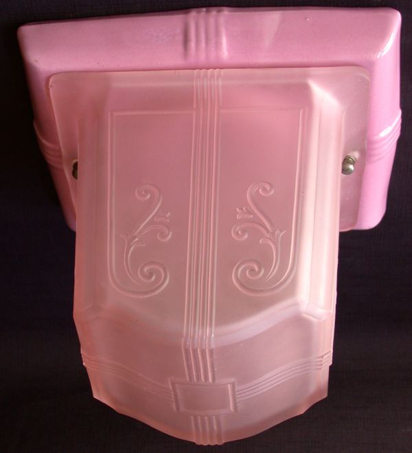
Changing a light fixture can be more involved than simply replacing a switch or a receptacle. Switches and receptacles almost always are housed in electrical boxes, but this isn’t always true for light fixtures. If the system is old or has been hacked at enough, you can disassemble an old ceiling light only to find a couple of wires dangling through the plaster without the hint of a box. As you should know by now, this is a dangerous situation because all wire connections must take place within a box. You might feel like cheating by continuing the status quo, but don’t. You’ll need to install a new box (unless one’s already there).
Lights usually get replaced because tastes change. Old fixtures don’t often wear out, since they have no moving parts (unlike a switch). Historic or not, the original hanging lights in your Craftsman home might be ugly to your eyes, or you might want to replace more modern fixtures with replication period fixtures to restore your home closer to its original condition.
The usual safety precautions apply to replacing fixtures that apply to any other electrical work—turning the power off is number one—but now you’ll sometimes be working off a ladder. For that matter, two of you might be working off two ladders if you have to remove an especially heavy or delicate fixture such as a chandelier. One thing is for certain: With the huge selection of new fixtures to choose from, you’re bound to find a replacement that will dress up any room in your house.

Considerations in Choosing Light Types


The most comfortable light in many instances is natural sunlight. (You may think differently if you live in the Sahara desert.) If you’re remodeling or adding on to your house, think about adding more windows and skylights. Millwork companies can custom match any existing wood window or come close enough with stock material. There are enough vinyl and aluminum window manufacturers around that you should be able to find one that will look like part of your house. Paint color also affects the impact of light, both natural and electric. Light colors will be the most reflective, but they might not be your first choice in certain rooms. Balance out your color choice with adequate lighting. Finally, look at your choice of controls or switches. Dimmers are inexpensive, and they greatly expand your options in any room. One minute your living room is washed in light for your Scrabble club’s monthly game; the next minute it’s dimmed way low for you and your jo. (Scottish for “sweetheart,” this word works great on a triple-word score.)

What to Do of Cheap Power Reigns?


At one point in the 1980s, it was estimated that the cost of residential electricity in Seattle was one tenth the cost in New York City. If it’s any consolation, our delicatessens weren’t anything to write home about. The cost differential isn’t that great anymore, but we’re still below the national average. Lower costs aren’t necessarily a justification for excessive use of electricity, but they will determine whether more efficient fluorescent lamps will ever pay off for you.
Basically, the higher your electricity costs run beyond the national average (around 8¢ per KWH), the more cost-effective fluorescent lights will be in your home. This doesn’t mean they will work well for all your lighting needs from a cost standpoint. The longer a light is continually on, the better a candidate it is for a fluorescent lamp. An occasionally used attic or storage-room light is best left with an incandescent lamp. Some fixtures, such as recessed ceiling lights, might not have room for a fluorescent lamp.

Wednesday, October 28, 2009

Fluorescent Lighting


Fluorescent lamps are considered to be the most energy efficient, but they often suffer from a reputation as flickering, eerie sources of light suitable only for institutional settings. They are the light source of choice in industrial and commercial settings because of their efficiency and long life—something worth considering for your home as well. Modern fluorescent fixtures have a place in residential settings.
A fluorescent lamp is constructed with …
  • A glass tube.
  • Argon or argon-krypton gas and a small amount of mercury.
  • Phosphor coating on the inside of the tube.
  • Electrodes at each end of the tube.
As electricity passes between the tube’s electrodes, it jostles the mercury atoms, which then give off ultraviolet radiation. The radiation is converted to light when it interacts with the phosphors lining the tube. The fixture itself comes with a ballast to kick-start the current passing within the tube and to keep it regulated. The range of phosphors available to manufacturers enables them to produce lamps with different color tones for different applications.
Fluorescent fixtures also produce less heat and more light for the amount of electricity they consume as compared to incandescent lamps.
One of the biggest changes in fluorescent technology is the shape and size of the lamps. In the past, you were stuck with straight, U-shaped, or circular figures. (The last always seemed to be used outside small-town, drive-in, ice-cream stands for some reason.) Now we have compact fluorescent lamps that can be an efficient substitute for incandescent lamps. A 40-watt compact fluorescent lamp, for example, can replace a 150-watt incandescent lamp and can last up to 10 times longer. (It had better, given the typical cost of $20 or more.) Two types of replacement units are available:
  1. Integral units, which include a compact fluorescent lamp and ballast in a self-contained unit
  2. Modular units, in which the bulb is replaceable Now you know that you can replace your incandescent lamps with compact fluorescent lamps, but is it worth it?

Tungsten-Halogen Lamps


These lamps (which are smaller in size than standard incandescent lamps) also heat up a tungsten filament, but they contain halogen gas. The gas combines with the evaporated tungsten to create tungsten halide gas that deposits the tungsten back onto the filament, extending its life. After the deposit, halogen gas is released and the process starts all over. The smaller size of the lamp enables the filament to heat up to a higher temperature and a higher efficiency.
Because none of the tungsten is deposited on the glass, a halogen lamp burns brighter and has a very focused, intense light.

Incandescent Lamps


This is the most familiar type of lamp. An electric current passes through and heats a tungsten filament, producing a glowing light. (The term “incandescent” literally means “to glow or become hot.”) Over time, heat evaporates the tungsten, and it eventually weakens and breaks. The lamp contains a chemically inert gas that allows the tungsten vapor from the heated element to deposit on the sides of the glass. This is why standard incandescent lamps gradually become darker over time. If they are too small, the tungsten coating would turn them opaque, and they’d be useless as a source of light. Incandescent lamps are cheap to produce and are versatile in application, but they are considered to be impractical by energy conservationists as a source of light given modern alternatives. They produce a considerable amount of waste heat for the amount of current they draw, and they have a useful life of 750 to 2,500 hours depending on the lamp. Builders traditionally install incandescent fixtures because both they and the lamps are inexpensive and are not likely to meet any resistance from price-conscious buyers. When buying lamps, take note of the voltage rating of the lamp. Typical lamps sold in stores are rated at 115 or 120 volts. At professional lighting stores, you should be able to find longer-lasting lamps rated at 130 volts.

Monday, September 28, 2009

What’s Your Lighting Type?


Lighting is divided by the type of lamp used and the style of the fixture. Lamp types include …
➤ Incandescent.
➤ Fluorescent.
➤ Halogen.
Each of these has distinguishing characteristics, as described in the following list. When it comes to fixture styles, the sky’s the limit. They range from antique reproductions to one-of-a-kind works of art (with prices to match). The following are some of the most common light fixtures:
➤ Flush-mounted ceiling lights that include square, mushroom, or round domes
➤ Hanging ceiling lights and chandeliers
➤ Surface fluorescent lights
➤ Recessed ceiling lights
➤ Track lighting
➤ Bath bars
➤ Sconces and wall-mounted lights
➤ Wall washes
➤ Undercabinet-mounted lights
➤ Outdoor lights (floodlighting, landscape lighting, pole-mounted lights, wallmounted lights, and security lighting)

All of these will light up a given area. You just have to decide whether they will provide light that you find both appropriate and pleasing to the eye. Your budget also is a consideration, especially if you’re buying fixtures for a major remodel. An outdoor landscaping light, for example, can be a simple pagoda light or an ornate—and expensive—leaded-glass lamp. (The latter is not recommended if you have kids, dogs, or errant adults running around the yard.)

Looks Are Something


The cheapest porcelain fixtures with 100-watt bulbs might provide safe lighting, but they won’t be much to look at. Visualize the appearance of the fixture and the lamp as well as their function. Some fixtures literally are works of art (Tiffany lamps, for example); others are designer-created and are very striking to look at. Do you want to look at a brass hanging light over the kitchen table or cobalt-blue steel? You’re going to be looking at them every day, so take your time choosing your fixtures.

Combining Lighting Styles


Most general living space will accommodate more than one lighting style. A closet
obviously doesn’t need accent lighting unless you make a point of giving your guests
a tour of your shoe collection. A dining room needs ambient light, but it can become
very dramatic with, say, floor-to-ceiling lights illuminating the side walls while the recessed
ceiling lights are off and a few lit candles are on the table. A mix of lighting
offers the most options and can present a room and its occupants at their best in a
variety of settings.

Whether you’re building something new or remodeling, keep your furniture in mind
rather than strictly installing lights by formula (so many per square feet at such and
such a distance from each other). You might have a grand piano ready to nestle in a
corner of the living room or a windowless wall just waiting for your collection of
family portraits. Either situation calls for very specific fixture placement.

Friday, August 28, 2009

Lighting Up Outside


I think exterior lighting is always a plus with any. Good lighting will welcome you and your guests on a rainy night, provide some measure of security for your family, and illuminate address numbers, door locks, and staircases. Before you decide to install fixtures as powerful as Batman’s searchlight, consider the following:
  • Know the size of the fixture and its scale compared to your house.
  • Think about the location and aim of the lights and their effect on your neighbors. (A little light goes a long way at night.)Caulk the top seam between the fixture and the section of the house where it’s attached to ensure that water stays out. Leave the bottom uncaulked so that, if moisture does get in, it has a place to exit.
  • Think twice before installing solid-brass fixtures. They won’t rust, but eventually most will tarnish and need polishing.
Installing outside lighting, like many tasks, can be done the easy way or the hard way. The easy way means mounting all the fixtures on the walls of your house (and porch ceilings), which means you can pull your wires from inside the house. The hard way means digging ditches and running wires and conduit underground, although this will give your yard a much more dramatic presentation. As a final consideration, think about what your outdoor lighting will look like from inside the house. You can enjoy your yard even in the winter if you set up lighting that accents it well.

Aim the Lighting High, Low, and Wide


Light from a lamp is aimed somewhere, whether it’s the top of your desk or your workbench. Even general ambient lighting gets directed somewhere. Recessed ceiling lights and adjustable spotlights can provide as broad or as focused a beam of light as you desire. Some lights are installed as wall washers, meaning they shine down a wall either to highlight artwork or other collections or simply to draw your attention to the perimeter of the room, conveying a greater sense of size than might truly exist. The advantages of recessed ceiling lights are their versatility and unobtrusiveness. Let’s face it, a chandelier automatically draws attention to itself—especially if one of your party guests is swinging on it. A recessed fixture is far more subtle and almost hides in the background.
Some fixtures can serve more than one purpose. A wall sconce, for example, can serve general, task, and accent lighting needs. This versatility is a huge advantage over ceiling lights when you’re remodeling because it’s far easier to wire and install a wall fixture than to install most ceiling fixtures.

Know Your Lighting


Lighting is defined by its use in our homes and places of work. Designers and architects break it down into several categories:

➤ Accent lighting emphasizes or highlights a specific area or object and directs our attention to it.
➤ Ambient lighting is general illumination.
➤ Task lighting is for illuminating work and tasks.

It’s never a bad idea to install plenty of ambient lighting, even if you later decide it’s more than you immediately need. At some point in the future, you might move things around and decide you need more lighting. I wouldn’t recommend tearing up the walls just to install fixtures, but if you have an open ceiling or already are doing some installations, consider a few extra light fixtures if the circuit permits. If you walk into a lighting store or the lighting section of a home-improvement center, you’ll see dozens and dozens of fixtures to choose from. Where do you start?

Tuesday, July 28, 2009

Distinguishing a Lumen from Illuminance


Light output is measured in lumens. According to The American Heritage Dictionary of Science, a lumen is a unit of luminous flux equal to the amount of light from a source of one candela radiating equally in all directions. A candela is a unit of luminous intensity equal to 1/60 of the radiating power of one square centimeter of a black body at 1,772°C. You can draw two conclusions from this information:
  • The higher the lumen measurement, the more light you’ll have to work with from a fixture.
  • Authors can easily get carried away when they have too many reference books at their disposal.
Illuminance, which is measured in foot-candles, is the amount of light hitting a point on a surface. A foot-candle is (easily enough) defined as the amount of light produced by one candle on a surface one foot away. We can’t see illuminance, but we do see luminance or brightness, although this is somewhat subjective. (What appears to be dim light to me might be plenty bright to you.) Architects and lighting consultants take all these measurements into consideration when they calculate the lighting needs of buildings.
Comfortable lighting selections and light levels are determined by the tasks that require the lighting, the distance between the light and the task, and the degree of glare. One definition of glare is excessive contrast between the intensity of light on a particular object or surface and the surrounding area or background; indirect glare is the glare produced from a reflective surface. Too much contrast between them causes glare. (Computer screens are a common example.) You can reduce this glare by …
  • Installing fixtures that keep the light level appropriate for the task at hand.
  • Using a louver or a lens to block or redirect the light.
  • Carefully considering the placement and spacing of light fixtures.
Another measurement of lighting quality is how well it enables you to see colors accurately. The better the color rendering, the more pleasing the living space. Color-rendering capability is based, naturally enough, on the color-rendering index (CRI), which measures from 1 to 100. (Natural daylight measures at 100.) The higher the rating on the CRI, the more lifelike and accurate the object being viewed.

Measuring Your Lighting Needs


The NEC calls for a minimum calculation for general lighting and receptacle loads of three watts per square foot of living space. This comes out to approximately one circuit every 575 square feet. That doesn’t amount to a lot, but remember, electrical codes only establish minimum standards. In reality, you’ll want lighting everywhere.
Consider the different areas of your house and their individual needs:
  • Kitchen. Overhead lighting, natural light from windows and sliding doors, work light over counters, a light over the stove.
  • Bathrooms. Primarily lights over the sink(s) and lights over the bathtub and toilet, depending on the size of the room.
  • Dining room. A hanging light over the table, recessed ceiling lights, or possibly wall sconces. This room often has a dimmer switch to tone down the light.
  • Bedrooms. Children’s rooms often get ceiling lights. Master bedrooms might depend more on reading lamps and switch-controlled receptacles, although large rooms can use recessed ceiling lighting as well.
  • Hallway. You might want a long track light to highlight artwork on the walls.
  • Garage. At least one light per bay over the hood of the cars. It’s even better to add one or two at the other end so the trunks are illuminated.
  • Basement. Depends on whether the space is finished or unfinished. In either case, you want at least enough ceiling light to cover the entire area thoroughly, leaving no dark spots.
  • Closets, storage rooms. At least one ceiling light.
  • Outdoors. At a minimum, one light over each entry door and over the garage doors. It’s even better to consider lights to line walkways and illuminate gardens or security lighting for back and side yards.
Your use of a room obviously will determine your choice of lighting fixtures, their locations, and their number. A single fluorescent ceiling light will fulfill all the working requirements of most closets because the requirements are pretty basic: to shed enough light for you to identify and choose your clothes. A kitchen, on the other hand, requires all kinds of light for a modern homeowner. You need lights over counters for close work so you can chop, dice, and mince vegetables instead of your fingers. Overhead lights enable you to read the newspaper and get a better look at what’s hiding in the back of your pantry. A dimmer-controlled hanging light over the eating area lets you tone things down for a late-night meal. Anywhere you’ve got a wall, ceiling, or floor, you can install a light. It’s simply a matter of extending a circuit or running a new one and choosing your fixtures. The science of lighting is a little more complicated.

How Illuminating my home is.......


We are way beyond the point when lighting was simply functional, allowing us to work and not stumble around after the sun went down. If function was all it meant to us, every room in our house would have one huge, efficient, fluorescent light fixture on the ceiling and maybe a night-light or two for after dark. Instead, lighting does much more such as …
  • Create a mood or atmosphere.
  • Define a space.
  • Provide security and safety.
  • Highlight artwork or a section of your home.
Your lighting needs will be defined by these factors and others. Before you install a particular type of lighting, ask yourself the following questions:
  • Who will be using this area and for what purpose?
  • Do I want a traditional or modern look?
  • How often will anyone be in this room?
  • How much am I willing to spend?
  • Is energy conservation important to me?
At a minimum, the code calls for one switch-controlled light per habitable room. Hallways, stairways, and garages also must meet this code requirement. This can be accomplished with permanent fixtures, such as ceiling lights, or through a switch-controlled receptacle into which a lamp can be plugged. Bathrooms and kitchens, however, must have an installed fixture. Your first step is to establish your minimum lighting needs and then choose the style of fixture you want to meet them.

Tuesday, June 23, 2009

Grounding an Old Receptacle


A properly grounded system ties each device, appliance, and fixture back to the service panel with a separate grounding conductor (the bare copper or green insulated copper wire). It’s unrealistic to attempt this with an old electrical system unless you’re replacing it (in which case, the grounding would be part of replacing the system). You also could install a GFCI in place of an existing, two-wire receptacle. The National Electrical Code allows an ungrounded, two-wire receptacle to be replaced with a GFCI. A GFCI can even protect any receptacles downstream (away from the panel or power source). A GFCI used in this manner will only protect you from ground faults; it will not act as a ground for any equipment plugged into the receptacle(s). As a rule, it’s best for GFCIs to protect only a single box, not multiple receptacles. If you try to use one GFCI to cover multiple receptacles, you might experience nuisance tripping due to the greater sensitivity to current fluctuations. A GFCI installed to replace a twowire receptacle should be marked “No Equipment Ground.” A GFCI must be wired according to stamped terminals on the back of the receptacle. They will be marked “Load” and “Line” as well as “Hot” and “White.” The hot wire (which runs from the panel or fuse box) is the line conductor; anything going off to another load or receptacle is the load conductor. How do you know which is which? You’ll need your voltage tester.
With the power off and the old receptacle removed, separate all the wires in the box so they’re not in contact with each other (or with the box if it’s metal). Turn the power back on, and put one end of your probe on one hot wire and one on the neutral that is paired with the hot you are testing. If the bulb doesn’t light up, try the other black wire and neutral. The one that lights up the tester’s bulb is the line conductor. It’s the one receiving power from the current you switched back on at the service panel or fuse box. Connect this to the “Line,” “Hot” side of the GFCI. It is very important that the line side hot and neutral conductors or wires be connected to the “Line” side of the GFCI; otherwise, the GFCI will trip or will not work at all. If the line and loads are reversed, the GFCI will still have power if it is tripped, producing a hazardous situation.
As an alternative to installing a GFCI to replace an ungrounded receptacle, it is permissible to install a grounding conductor to an ungrounded circuit by using an individual No.12 insulated green copper conductor to connect each receptacle being grounded to the closest cold-water pipe. The grounding conductor will then have to be secured to the pipe using an approved clamping device. It also can be run directly back to the panel and installed in the grounding/ neutral bar.

Installing a New Receptacle


Receptacles are a little more straightforward than three- and four-way switches. With a single duplex receptacle, you’re dealing with one or two cables coming into the box. An end-of-the-run receptacle will have one cable, and a middle-of-the-run will have two. The receptacle has two sets of terminal screws, silver for the neutral wires and brass for the hot.
After shutting off the power and testing the terminal screws, remove the outlet by loosening the screws attaching it to the box. Remove the hot and neutral wires, noting their position on the outlet (hot upper, hot lower, neutral upper, neutral lower) by marking the position on an attached piece of masking tape. Reconnect to the new receptacle in the same locations, and gently push the wires back into the box while reattaching the new receptacle. Turn on the power at the service panel or fuse box and test.

Two-Wire Grounding


Do the following to test a two-slot receptacle: Place one probe in the hot slot and the other end on the screw securing the cover plate. The screw must be clean as well as paint and grease free.
  • If the receptacle is grounded, the tester’s bulb will light up.
  • Put the probe in the neutral slot if the tester does not light up in the hot slot. If it lights, the receptacle is grounded, but the neutral and hot wires have been reversed and are attached to the wrong terminals. If the bulb doesn’t glow at all, the receptacle isn’t grounded.
  • To be absolutely sure that the receptacle is grounded (if your test indicates that it is), turn the power off and remove the cover plate. Check to see if an actual grounding conductor is present.

Wednesday, May 27, 2009

Test for Grounding


You can test a grounded, three-slot receptacle for grounding (remember, the power is on) by placing one probe of your tester in the short slot and one in the hole for a plug’s grounding pin. The short slot is for the hot wire. The bulb should glow to indicate that the receptacle is grounded. If it doesn’t, keep one probe in the grounding hole and place the other one in the longer, neutral slot. In this position, if the bulb glows, it shows that the receptacle is grounded, but the black and white wires have been reversed (they’re attached to the wrong terminal screws) and should be corrected. If the bulb doesn’t glow in either case, the receptacle isn’t grounded. A three-slot receptacle that isn’t grounded is misleading and dangerous to a user. It might indicate that only the individual receptacle is incorrectly wired or that it was inadvertently used to replace an ungrounded receptacle. Either way, you want to know so you can correct the problem.

Check and Check Again


Receptacles, like switches and fixtures, need to be checked with a voltage tester before you do any work on them. The test is similar for both grounded and ungrounded receptacles, except you’ll be testing for grounding as well with the former. A grounding test can only be done with the power on.
With the power off, insert both ends of your voltage tester into the slots of the receptacle. The light in the tester should not go on. If it does, the power has not been turned off, or the wrong circuit was shut off. Even if the tester bulb does not light up, you can’t be sure that the current is off. The receptacle might be damaged but still receiving a current. Remove the cover plate and carefully pull the receptacle out. Place one probe on the brass terminal, which should be connected to the black or hot wire. Place the other probe on the silver or neutral terminal. You must touch both terminals to complete the circuit. The bulb shouldn’t glow if the power has been shut off.

Disreputable Receptacles


Receptacles are pretty long-lasting, but old ones eventually can give out when the clips no longer hold a plug snuggly. There also are drawbacks to some old receptacles if they’re neither polarized nor grounded. Receptacle bodies also get broken if furniture or toy trucks somehow bang into them. (This happens at gyms all the time, only barbells do the damage.)
You want your receptacles and their cover plates to be intact. Broken or missing sections can set up you and yours for a shock or worse. When replacing an old receptacle, you can’t simply pop a new, grounded receptacle into an existing two-slot outlet. It doesn’t work that way, although there is a trick you can do with a GFCI that will give you some protection, but it will not ground any equipment plugged into the receptacle. A GFCI does not give grounding protection unless a grounding conductor already is present.

Sunday, April 26, 2009

Old Wire, New Switch


It can be difficult working with the deteriorated knob-and-tube wire ends inside a box. You might have to snip off the end, and the remaining wire can be a little too short to easily connect to a new switch or receptacle. In this case, you can pigtail a short, new piece of wire to the existing wire and connect the pigtail to the terminal screw on the device. This also will bring the wires into compliance with the NEC, which calls for six inches of workable wire length inside a box. The following diagram shows this type of pigtail.

Dimmers


You can replace any interior single-pole switch with a dimmer if the box is large enough to accommodate the larger body of the dimmer. Don’t try to pack it into a tight or overcrowded box because this is a fire hazard (see the instruction sheet that comes with the dimmer). Dimmer switches come with about four inches of their own wiring or lead wires (line and load and ground wire) ready to connect with cable from the circuit with wire nuts.

The Great Outdoors


You cannot replace an outdoor switch with an indoor switch unless you also use a bubble-type cover or a cover with a flip-style lid. These are weatherproof covers. Better yet, you can use a cover with a built-in, horizontal, lever-type switch that comes with a foam gasket between the cover plate and the box. The lever activates a regular toggle switch underneath. Other than that, the replacement procedure is the same as a regular single-pole switch.

Saturday, March 28, 2009

Four-Way Switch


A four-way switch has two sets of traveler wires running between it and a pair of threeway switches. There is no common wire nor is there a common terminal. The continuity test for a four-way switch requires a few extra steps. You need to put the clip on any pair of traveler screw terminals separately and then touch each of the other screws with the probe. This is a total of six tests for each position of the toggle (see the following figures). The test should show two continuous currents for each position of the toggle switch. (The paths between specific traveler screw terminals vary with different manufacturers.)

A four-way switch box has two cables with three conductors coming into it (thus four hot conductors or wires). Two are black; the other two are a second color, most likely red. When you replace the switch, be sure to match the wires to the correct traveler terminals. New four-way switches either match their terminals up by color (two are brass and two are copper), or the back of the switch might have wiring instructions. This makes your job easier. You simply have to match one color of wire insulation to one set of screws (red wires to brass screws, for example). See the following figures for a typical installation.

Three-Way Switch


Replacing a three-way switch is more involved than replacing a single-pole variety. Now you have traveler wires to deal with (these connect the two three-way switches) as well as the common wires.
This means the cable running between the switches is 12/3 (or 14/3) cable rather than the more common 12/2 (or 14/2).
Follow the same safety and testing procedures that you would with a single-pole switch. Because three way switches (and four-way switches) are more expensive than a common single-pole switch, you want to be certain that the switch is really broken before throwing it away and replacing it. When removing a three-way switch from its box, note to which terminal screws or
back-wired slots the wires are connected. Mark the common wire with a small piece of masking tape, or attach each wire to the new switch as you remove them from the old switch. The common terminal screw usually is copper; the traveler terminals are brass or sometimes silver. Note whether the neutral wire is being used as a hot conductor.

New Switches


The easiest switch to replace is the single-pole switch. Before popping in a new one—and this is true with any device—read the specifications on the old switch. These usually are listed on the metal mounting strap and include the following:
  • The amperage and voltage ratings
  • The type of current it will carry (AC only for house current)
  • The type of wire that’s compatible with the device (CU for copper only, CO/ALR for copper or aluminum, ALR for aluminum only)
  • Its Underwriters Laboratory or other testing service listing

The back of the device will indicate the acceptable wire gauge and a stripping gauge for measuring the amount of insulation to be removed prior to installation. The location of your switch will determine how its replacement gets wired. A switch can be at either the middle or the end of a run (one complete circuit). These positions in the run are simply defined:
  • A middle-of-the-run switch can be anywhere between the beginning and the end of the circuit. There will be at least two cables entering the box (at a minimum, one on the line side coming from the panel and one leading to a fixture or other device).
  • In an end-of-the-run switch (also referred to as a “switch loop”), the cable runs from the fixture to the switch. This requires special treatment of the white wire.

Remember to shut the power off at the service panel or fuse box and to test the switch with a voltage tester before removing the wires. Note the condition of the ends of the wires. You don’t want to reuse damaged or nicked wires. If you find any damage, cut off the minimum amount of wire necessary to remove this section and then strip off sufficient insulation (about 5/8 of an inch) so the wire will make a solid contact.

Wednesday, February 25, 2009

Continuity Coming Up

A continuity test will tell you whether a switch’s metal components, which are critical for the flow of the current, are intact or broken. A continuity tester is battery-powered and provides a current that passes from the tester’s clip through a device or fixture. The tester’s other component is a probe that lights up if a current is passing through the device as designed. To perform the test, a switch or fixture must be disconnected from its power source and removed. (The tester will supply the current for the test.) A continuity tester should never be used on a live current.
The following figures show you how to do a continuity test on a single-pole switch and a three-way switch. If your tests show you that the switch is the problem, it’s time to replace it.
If your tests show you that the switch is the problem, it’s time to replace it.

Checking the Devices

Switches, appliances, and fixtures test a bit differently than receptacles. The first three are tested for continuity and power and require both testing tools. A continuity tester will indicate whether the circuit’s pathway within the switch has any breaks in it from metal fatigue. It also checks other appliances and fixtures for similar breaks. Let’s start with testing for a switch.
Follow these steps to test a switch for power:
  1. With the switch off, touch one of the voltage tester’s probes either to the bare end of the ground wire (the inside of the wire nut holding the neutral wires together) or, if it’s a metal box, to the side of the box.
  2. Place the other probe against each black wire either at the terminal screw or at the back-wired slot.
  3. The bulb should light up for at least one of the hot wires, the line wire coming from the panel or fuse box. If the tester does not light up for either black wire, the problem is somewhere in the circuit between the panel and the device. (Go to step 4 if it does light up.)
  4. Turn the switch on and check the other black wire, which is the load conductor. If the bulb on the tester does not light up, the switch is bad and needs to be replaced.
  5. If both black wires show current passing through them, recheck the fixture and the appliance because the problem is not with the switch.
  6. Note: In some older homes with knob-and-tube wiring, the neutral wire has been switched and used as a “hot” conductor. This makes the task of troubleshooting much more difficult. If you have any questions or concerns while testing, call an electrician.

Wednesday, January 28, 2009

Probing the Problem


You flick the light switch and nothing happens. The coffeemaker, which was set on a timer to go off at 6 A.M., sits with pot of cold water on your kitchen counter. Before assuming that the devices are shot, follow this checklist:
  1. Confirm that the circuit has power and that the fuse hasn’t burned out or the circuit breaker tripped.
  2. Check to see if the appliance or fixture is working by checking light bulbs, cords, and plugs.
  3. Inspect the connections at the fixture and at the terminal screws to ensure they are tight.
  4. ❏ Check for a problem in the circuit itself.
The very first thing you should do is confirm that power is getting to the device. Every electrician has a story about going on a service call to repair a dead circuit only to discover that the breaker had tripped and no one checked. That’s a pretty expensive discovery for a homeowner. Your first step is to examine your fuse box or service panel. Does everything look okay? Are there burned-out fuses or tripped breakers for that circuit? Check carefully. Some breakers have very little sponginess and don’t move much when they trip. You might have to test several breakers if you haven’t done a circuit map and are uncertain which breaker controls the failed device. If you can eliminate the power source as the problem, check the connections (see the following figure) by taking the following steps:
  1. Turn the power off.
  2. Remove the cover plate from the device, and unscrew the device from the box.
  3. See if the terminal screws are tight and have good contact with the wires.
  4. If the device is back wired, there shouldn’t be any bare wire showing, only insulation.
  5. Check the wire nuts or taped-and-soldered connections to be sure they’re tight.
If there are no problems with the connections, you’ll have to probe further with your handy voltage tester and a continuity tester.

Replacing Old Switches and Receptacles

Now that you know about switches and receptacles, it’s time to replace any that are broken or to upgrade existing ones. The most common upgrade is swapping a standard toggle switch for a dimmer. Newer, quieter models—that don’t have the resounding “click” of old switches—sometimes are installed in older homes that still have their original devices.
The most common reason for replacing a device is wear and tear. The clips in a receptacle that hold a plug tautly or the metal arm in a switch eventually can fatigue and no longer work properly. A simple loss of power to a fixture or an appliance, however, is not necessarily a reason to replace a device. You have to do a few system checks first, which we’ll discuss in this chapter.
The short projects in this chapter will help you get your feet wet—don’t take that literally, however, when working around electricity—and gain a degree of comfort with your electrical system. Three- and four-way switches require more troubleshooting skills, but we’ll cover the most common situations with both switches. We’ll also discuss upgrading your current two-wire receptacles and making them safer when the situation calls for it—without updating the entire system with a grounded conductor.

Brass: New and Old


Many older homes have original brass cover plates, often with a dark bronze tone. These will readily take to a buffing wheel and will come out a fine, shiny brass if that’s your preference. New replacement brass plates also are available. Some homeowners and designers install them in kitchens and bathrooms, but such damp locations aren’t the best places for brass unless you like polishing them from time to time. If you go to any good-size street fair, at least in a large city, you’re likely to run into an artist’s booth selling ceramic electrical plates. Some have a theme (such as stars or suns); others are a little more whimsical. Check to see if they’re listed by UL; if they’re not, decide whether you think it’s a problem. These plates are usually ceramic, nonconducting material and can be pricey.
Local gift and design shops might carry these types of plates as well. They usually are purchased for a single room, such as a bathroom or a baby’s room, rather than an entire home.

Monday, January 12, 2009

Cover Plate for Cable Boxes


Every electrical box needs a cover plate. A junction box, which is used solely to house wires and their connections but not devices, needs a blank cover plate. The cover plate keeps probing fingers, especially those of kids, away from the wires and the terminal screws on the device, all of which are fine sources of electrical shock. Plastic is the material of choice for most cover plates, but metal is used in some commercial work and with metal boxes. Outdoor boxes have plates with foam gaskets to keep moisture out. Outdoor receptacles have additional protection: A section of the cover plate closes over and covers the receptacle when it isn’t in use. Plastic cover plates have been used since the 1920s, but other materials have been used as well.

Brass: New and Old
Many older homes have original brass cover plates, often with a dark bronze tone. These will readily take to a buffing wheel and will come out a fine, shiny brass if that’s your preference. New replacement brass plates also are available. Some homeowners and designers install them in kitchens and bathrooms, but such damp locations aren’t the best places for brass unless you like polishing them from time to time.

The Artful Flare of Ceramics
If you go to any good-size street fair, at least in a large city, you’re likely to run into an artist’s booth selling ceramic electrical plates. Some have a theme (such as stars or suns); others are a little more whimsical. Check to see if they’re listed by UL; if they’re not, decide whether you think it’s a problem. These plates are usually ceramic, nonconducting material and can be pricey.
Local gift and design shops might carry these types of plates as well. They usually are purchased for a single room, such as a bathroom or a baby’s room, rather than an entire home.

Check the Cable Box Size


Boxes come in different sizes based on the installation need. Rectangular boxes, the most common ones used for single devices, generally are two inches by three inches for residential use. Depth ranges from 15/8 inches to 319/32 inches. The deeper the box, the more wires it can accommodate and the easier it is to tuck in the wires and install a device and still meet code. You’ll really appreciate this when you’re dealing with 12-gauge wire.
A round box with
extendible bars.
How many cables can your box accommodate? Well, the bigger the box the better, but to be more exact …
  • Count the number of intended cables for the box. Each hot and neutral conductor counts as one wire each, and all the grounding conductors together count as a single wire.
  • Take this total and add one for any cable clamps (if they’re the same type of clamp). If you have two different types, you have to count each as a separate number.
  • Take this new total and add two for each device (switch or receptacle).
  • If the box contains 14-gauge wire, multiply the total number (of wires, clamps, and devices) by 2 cubic inches. If 12-gauge wire is being used, multiply the total by 2.25 cubic inches.
  • The result of this multiplication is the minimum allowable volume of wires, clamps, and devices for that box.
(The volume of a box usually is stamped on the back of the inside of the box.)
Let’s say you have a light switch in a plastic box with two 14-gauge cables coming
into it. (One is the line; one is the load.) This gives you two hot conductors, two neutrals,
two grounding conductors (these count as one wire in our calculations), and
one switch. Therefore …
Two hot conductors: 2
Two neutrals: 2
One grounding conductor: 1
Device: 2
Total: 7
7 2 cubic inches = 14 cubic inch minimum box size (Note: Most plastic boxes do not have any type of clamp.)

Plastic or Steel Cable Boxes?


Both plastic and steel boxes are used in residential construction. A box has to withstand a certain amount of construction trauma when it’s installed and later when drywall is installed around it. (Drywall hangers are not necessarily kind and gentle people, at least not when they’re getting paid by the square foot.) Plastic boxes are lightweight and are easy to install, especially those that come with nails for direct attachment to a wall stud or a floor joist.
Metal boxes are standard in most commercial work. Unlike a plastic box, a metal box is a good conductor of electricity and must be grounded along with the device or fixture. Special fittings are used to connect a metal box to conduit and conductors to the box. These fittings include an array of clamps, clips, and locknuts, most of which you’ll never use in the course of residential repairs and remodeling. A plastic box works well for a single gang or device use, but some electricians find that a larger plastic box’s shape distorts during installation or when the drywall is installed. For these reasons, they use tougher boxes, either Bakelite (reinforced phenolic) or metal for two gang installations and metal for three gang. The larger the box, the more difficult it is to keep it level and in line.